

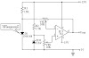
Digital To Analog Converter Circuit Diagram:

The voltage reference (D2) is common to all channels, but-the value of the dropping resistor (R9) varies as the number of DACs installed in the system. IC15 is a DAC0808 A/D converter chip. ICI6A is an op amp to interface the output current from the D/A convert to an analog voltage output.
Sourced By :w3circuits


0 Comments