

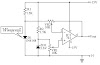
Circuit Diagram:

The scale adjust function is provided by the regulator output control, which is set to a nominal10 V in this system. The line-voltage regulation (approximately 0.2%) permits 9-bit accuracy to be maintained with a variation of several volts in the supply. System power consumption ranges between 70 and 200 mW; a major portion is dissipated in the load resistor and op amp.
The regulated supply provides a maximum current of 440 p,A of which 370 p,A flows through the scale adjusting. The resistor ladder is composed of 1 % tolerance metaloxide film resistors. The ratio match between resistance values is in the order of 2%. The follower ampliiier has the offset adjustment nulled at approximately a 1 V output level.
Sourced By :w3circuits


0 Comments