

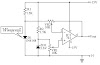
Universal Battery Charger Circuit Diagram:

The LM317 is connected to the battery through diode D1, limiting resistor R1, and bias resistor R2. The D1 diode is used to prevent the battery from discharging through the LED and the SCR when power is removed from the circuit. When LED1 is on, the circuit is in the voltage-regulating mode and when LED1 is off, the circuit is in the current-regulating mode.
Sourced By :w3circuits


0 Comments