

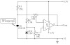
Low-cost Flashing Signal Alarm with LEDs Circuit Diagram:

The 200 to 400-dc supply should have enough internal resistance to charge the 0.5 capacitor between flashes, about 2 or 3 time constants, which means about 500 kQ to 1 for a 1-s rate.Use lower values for higher rates.The Signalalarmfunction shall cause the system to generate a SIGALRM signal for the process after the number of realtime seconds specified bysecondshave elapsed. Processor scheduling delays may prevent the process from handling the signal as soon as it is generated.


0 Comments