


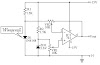
Following the count has reached binary 1111, the subsequently pulse sends the O4 output of IC3 high, which disables IC2c and IC3 stops with. The four used outputs of IC3 are connected to a resistor ‘ladder’ which acts to the same degree a clear-cut digital to analog convert-er (DAC). As the count increases so does the voltage produced by the side of the top of the ladder and this is connected to the inverting inputs of four comparators inside IC4 (an LM339) and to IC5, which is a 741 op amp furthermore connected while a comparator.
The categorical inputs of the comparators are connected to the taps of a voltage dividing wall, with the drumming voltages settle on using VR1, a 100kO trimpot. As IC3 counts, the rising stepped voltage from the DAC ladder switches the comparators on clothed in sequence, preliminary with IC4d and working up to IC5. in the same way as both comparator is curved on, its pair off of LEDs is lit; former LEDs 1 & 2, next LEDs 3 & 4 and so on. as soon as all five pairs of LEDs are lit, the then pulse from IC1 moves the binary count of IC3 to 10000, so the DAC voltage drops back to zilch and all LEDs are extinguished. by the same spell, with too stops, for the reason that the area of high pressure on O4 causes IC2c to check extra gate pulses. The circuit in that case remains reserve until the counter is reset by urgent pushbutton switch S1. This allows a recent sequence to initiate.
Sourced By:w3circuits


0 Comments