AVR device not responding, When this discouraging message appears while you’re programming your Atmel microcontroller, that’s where the problems really begin! The problem is of ten due to incorrect programming of the fuse bits.This is where the unblocking probe comes into play.
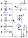
Once the whole thing is powered up, all you have to is use one hand to apply the tip of the probe to the microcontroller’s XTAL1 input and then use your other hand to go ahead and program it with your favourite sof t ware. And there, your microcontroller is saved! The electronics are as simple as can be, the aim being to design something cheap and easy to reproduce. It consists of an oscillator generating a rectangular wave at around 500 kHz, built using a 74HC04. This circuit will also work with a 74HC14, but depending on the make of IC, the frequency of around 500 kHz may vary by around ±50 kHz. This doesn’t affect the operation of the probe.
Reanimating Probe for AVR μC Circuit diagram :
The unblocking board is connected using a ribbon cable, terminated with two female HE10/10 connectors. The pinout of the HE10/10 connector is the same as used in the majority of circuits, but of course it can be adapted for an HE10/06 connector.
The first connector is connected to the board to be unblocked, which allows powering of the electronics. The second connector is connected to the ISP programmer (STK200 compatible). The contact at the crystal is made using a needle, to ensure contact even through a board that has been varnished. There’s no need to unsolder the crystal for this operation.
The PCB design in Eagle format is available from : www.elektor.com
Popular Posts

Simple USB Power Booster
April 07, 2018

Simple Steam Whistle
April 07, 2018

USB DC Power Supply from Cigar Lighter Socket
November 01, 2017
Tags
- power supply
- LED Drive
- hobby
- batteries
- charger
- led
- LEDs
- Solar
- Audio and Music
- Inverter
- chargers
- Alarm
- Battery Charger
- sensor
- Alarm and Securty
- Detector
- Lights
- various
- Analogue Design
- indicator
- 555
- Digital
- USB
- VU Meter
- amplifier
- camera
- ic555
- regulator
- Microcontrollers
- Securty
- Video
- automotive
- booster
- components of RS
- connectors
- control
- converter
- garden
- scanner
- switch
- telephone
- wireless
Random Posts
3/random/post-list
Recent Posts
3/recent/post-list


0 Comments